
SCA

Shinyei Corporation of America

  • HOME
  • PRODUCTS
    • WEATHERING, CORROSION, AND OPTICAL PROPERTIES
    • EMC EMISSION & IMMUNITY
    • DROP & SHOCK
    • VIBRATION
    • BALL BEARINGS
    • MECHANICAL & PHYSICAL PROPERTY OF MATERIALS
    • TEMPERATURE SENSING
    • ENERGY DISPERSIVE X-RAY FLUORESCENCE ANALYZERS
    • NO-DOOR ENVIRONMENTAL CHAMBERS
    • ENVIRONMENTAL & THERMAL SHOCK CHAMBERS
    • HUMIDITY, PARTICLE, AND GAS SENSING
    • CONTRACT TEST SERVICE
  • TECH RESOURCES
  • APPLICATIONS
  • NEWS
  • ABOUT
    • About SCA
    • Shinyei Group
    • SiteMap
    • Sitepolicy
    • Cookie Policy
    • Privacy Policy
    • Disclaimers
CONTACT
   
SCA

Shinyei Corporation of America

  • HOME
  • PRODUCTS
    • WEATHERING, CORROSION, AND OPTICAL PROPERTIES
      • Weather Meters
        • GX75
        • SX75
        • SX2D-75
        • S80
        • MV3000(Metal Halide Arc)
        • U48(UV Carbon Arc)
        • FUV(Fluorescent UV Lamps)
        • CCT-LXU
        • CCT-1LX
      • Light Sources
        • 7.5kW Xenon lamp & Sunlight
        • 3kW Metaling Lamp
        • Sunshine Carbon Arc
        • UV Fluorescent Lamp
        • UV Carbon Arc
      • Corrosion Test Chambers
        • CYP-90
        • CYP-120,160,200
        • CCT-1(L)
        • CCT-RX
        • STP-90V-5/CAP-90V-5
        • STP/CAP-110,120,160,200
        • Exhaust Disposal Unit
      • Optical Property Meters
        • Color Meters
        • Gloss Meters
        • Haze Meter
          • HZ-V3(DISCONTINUED)
          • HZ-V4 (NEW)
    • EMC EMISSION & IMMUNITY
      • ESD Simulator
        • IEC61000-4-2 Ed.2 Test Standard
        • ESD simulator(ESS-S3011A+GT-30RB)
          IEC61000-4-2 Ed.3 Test Standard (NEW)
        • ESD simulator(ESS-PS1+GT-31S)
          IEC61000-4-2 Ed.3 Test Standard (NEW)
        • ISO 10605 Ed.2 Test Standard
        • ISO 10605 Ed.3 Test Standard
      • Fast Transinet Burst Simulators
      • Impulse Noise Simulator
      • Lightning Surge Simulator
      • Lightning Surge Simulator for EV fast charging
      • High Voltage Noise
      • Field Decay Load Dump
      • TEM Horn Antenna
      • Thin Plate Broadband Antenna
        • Thin Plate Broadband Antenna(NKU07M32G/NKU2460G)
        • Thin Plate Broadband Antenna(NKU5080G) (NEW)
      • Electromagnetic Field Visualization System
    • DROP & SHOCK
      • Drop Test Systems
        • DT-202 series
        • DT-205 series
        • DT-20e
        • RDT-1000
        • EMH series
      • Shock Test Systems
        • HDST series
        • ASQ series
        • MDST series
        • SDST series
        • PST-300
        • CDS series
      • Material Testing System
        • ACST series
      • Acceleration Measurement
        • SM-500
        • AccStick
      • Field Data Recorder
        • DER-1000
    • VIBRATION
      • Products
      • Basics of Vibration Testing
      • Multi-Axis Vibration Test Systems
      • Single-Axis Vibration Test Systems
      • Vibration Combined Environmental Test Systems
      • Digital Vibration Controller
    • BALL BEARINGS
      • Stainless Steel Ball bearing by AFC bearings
      • Stainless Steel Ball Bearing
        • AISI 440C Stainless Steel Ball Bearings
        • AISI 304 Stainless Steel Ball Bearings
        • AISI 630 Stainless Steel Ball Bearings
        • 2C Series - Ceramic Bearings
        • Grease Free Bearings
        • 1T Series - Pure Titanium Bearings
        • SH series - Stainless Ball Bearing with Aligning Ring
        • SSXC Series - Stainless steel ball bearings with setscrews
        • SF series - AISI440C Flanged Bearing Units
      • Spherical rolling joint SRJ series
    • MECHANICAL & PHYSICAL PROPERTY OF MATERIALS
      • By Test Applications
      • By Test Properties
    • TEMPERATURE SENSING
      • Temperature Probes
        • Stationary Surface Temperature Probes
          • SX Series
          • WE Series
        • Moving/Rotating Surface
          Temperature Probes
          • U Series
        • Moving Wire / Tube Probe
        • Liquid / Semiliquid Probes (Needle type)
        • Special Application Temperature Probes
          • AW Series(for Wafer)
      • Thermometers
        • Handheld Thermometer Model HR series
        • Handheld Thermometer
        • Thermoprinter
        • Thermologger
        • Transducer (Transmitter) HPD Series
        • Non-contact thermometer
        • Soldering iron thermometer
        • Fiber optic thermometer
      • Application
      • Accessories
      • Technical Guide
      • FAQ
    • ENERGY DISPERSIVE X-RAY FLUORESCENCE ANALYZERS
      • VoXER
      • OURSTEX 170
      • OURSTEX 101FA
      • OURSTEX 100FA
      • OURSTEX 100TA-F
      • OURSTEX 200TX
      • OURSTEX 160
      • OURSTEX 160RoHS
      • OURSTEX 160M
    • NO-DOOR ENVIRONMENTAL CHAMBERS
    • ENVIRONMENTAL & THERMAL SHOCK CHAMBERS
      • Temperature and Humidity
      • Thermal Shock
      • Compact Temperature and Humidity
    • HUMIDITY, PARTICLE, AND GAS SENSING
      • Humidity Sensing
        • humidity Sensors
        • humidity and Temperature
        • Thermo-hygrometer/Recorder
        • Temperature humidity converter
        • TDLAS Moisture Analyzers
        • Humidity Generators
      • Particle Sensing
        • Particle Sensor Unit
        • Aerosol Sensor
        • Pollen Sensor
        • Large Particle Sensor
        • PM Sensor
      • IAQ Sensing
        • Handheld Odor Meter
    • CONTRACT TEST SERVICE
  • TECH RESOURCES
  • APPLICATION NOTES
  • NEWS
  • ABOUT
    • About SCA
    • Shinyei Group
    • SiteMap
    • Sitepolicy
    • Privacy Policy
    • Cookie Policy
    • Disclaimers
  • CONTACT

NOISEKEN

  1. HOME
  2. PRODUCTS
  3. NOISEKEN
  4. IEC61000-4-5 Ed.3 Test Standard Overview

IEC61000-4-5 Ed.3 Test Standard Overview

Shinyei Corporation of America is the sole authorized distributor of NoiseKen products. We offer the most direct sales of NoiseKen products available in the US.

  • Overview
  • Test Levels
  • Generator & Waveforms
  • CDN Waveforms
  • Test Setup
  • Test Procedure
  • Test Report
  • Telecom Lines

1. Overview

The purpose of this laboratory test is to evaluate the immunity of equipment under test (EUT) to unipolar surge disturbances under specified operating conditions. These surges simulate the effects of switching transients and indirect lightning-induced surges at defined threat levels.

This standard specifies two types of combination waveforms. One is intended for testing power supply lines and interconnection lines, using a 1.2/50 μs open-circuit voltage waveform and an 8/20 μs short-circuit current waveform. The other is intended for testing telecommunication equipment connected to outdoor telephone lines, using a 10/700 μs voltage waveform and a 5/320 μs current waveform.

This standard is not intended to evaluate the insulation withstand capability of the EUT under high-voltage stress or its ability to withstand direct lightning current injection (i.e., a direct lightning strike).

2. Test Levels

LevelOpen-circuit test voltage kV
Normal modeCommon mode
1–0.5
20.51.0
31.02.0
42.04.0
xspecialspecial

x: Can be any level, above, below or in between the others. The level shall be agreed upon between the manufacturers and users.

3. Waveforms Generator and Waveforms specifications

■ Generation Circuit
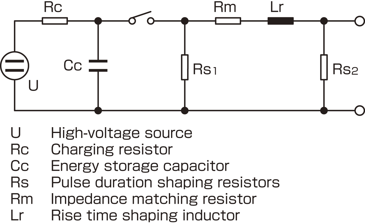
Generation Circuit

■ Voltage Surge (1.2/50μs)
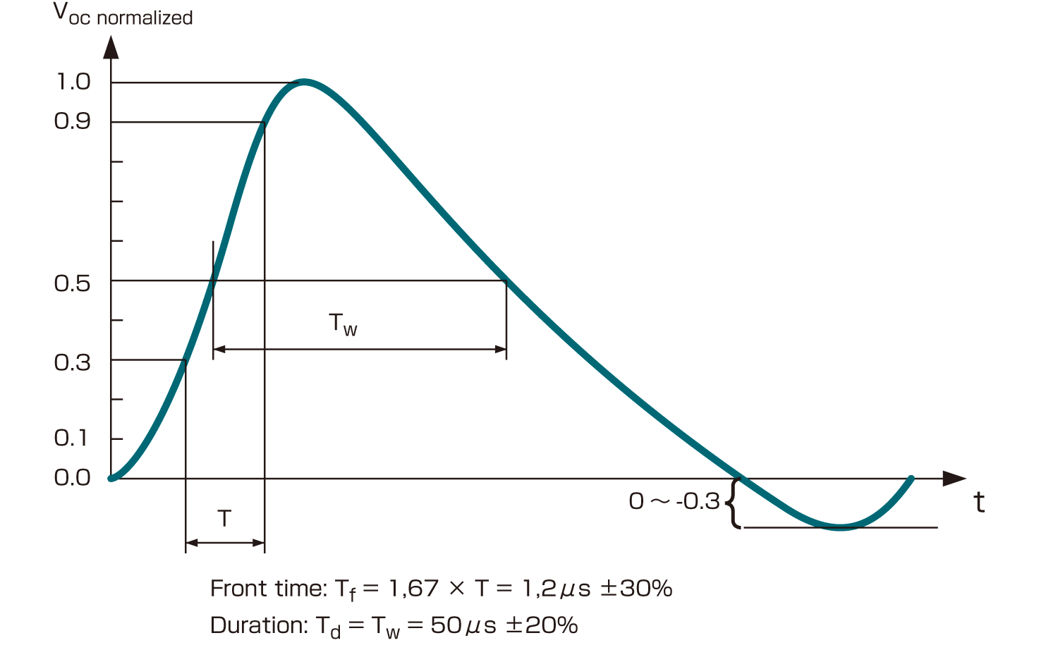
Voltage Surge (1.2/50μs)

■ Current Surge (8/20μs)
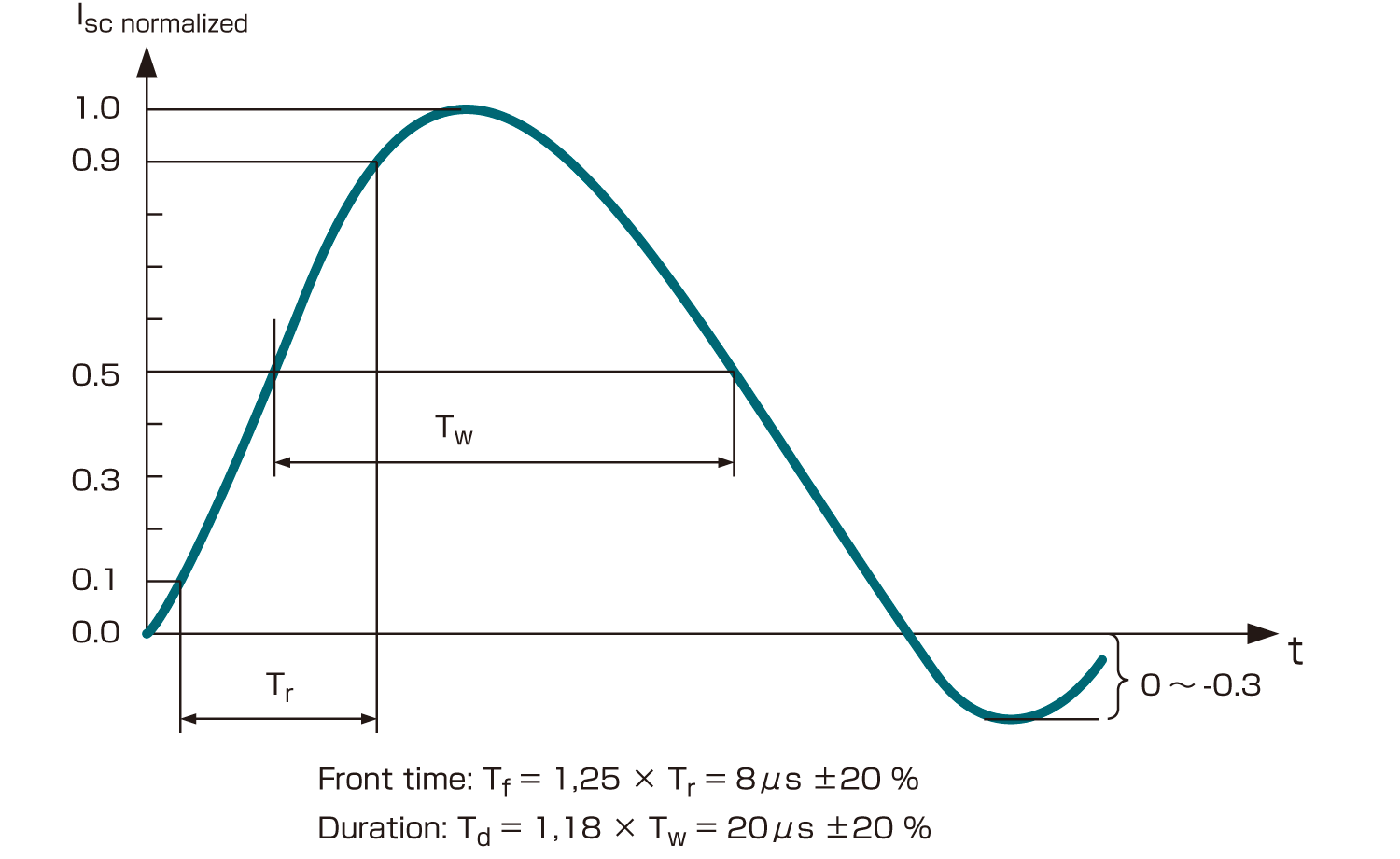
Current Surge (8/20μs)

■ 1.2/50μs Combination Waveform specification

Front time Tf µsDuration Td µs
Open-circuit voltageTf = 1,67 × T = 1,2 ± 30 %Td = Tw = 50 ± 20 %
Short-circuit currentTf = 1,25 × Tr = 8 ± 20 %Td = 1,18 × Tw = 20 ± 20 %

4. Voltage waveform specification at the EUT port of power line CDN

■ 1.2/50μs Voltage waveform specification at the EUT port of the power line CDN (open-circuit voltage)

Open-circuit voltage *Coupling impedance
18 µF (line to line)9 µF + 10 Ω (line to ground)
Peak voltage Current rating ≦ 16 A 16 A < current rating ≦ 32 A 32 A < current rating ≦ 63 A 63 A < current rating ≦ 125 A 125 A < current rating ≦ 200 ASet voltage +10 %/-10 % Set voltage +10 %/-10 % Set voltage +10 %/-10 % Set voltage +10 %/-10 % Set voltage +10 %/-10 %Set voltage +10 %/-10 % Set voltage +10 %/-10 % Set voltage +10 %/-15 % Set voltage +10 %/-20 % Set voltage +10 %/-25 %
Front time1,2 µs ± 30 %1,2 µs ± 30 %
Duration Current rating ≦16 A 16 A < current rating ≦ 32 A 32 A < current rating ≦ 63 A 63 A < current rating ≦ 125 A 125 A < current rating≦ 200 A50 µs + 10 µs/ -10 µs 50 µs + 10 µs/ -15 µs 50 µs + 10 µs/ -20 µs 50 µs + 10 µs/ -25 µs 50 µs + 10 µs/ -30 µs50 µs + 10 µs/ -25 µs 50 µs + 10 µs/ -30 µs 50 µs + 10 µs/ -35 µs 50 µs + 10 µs/ -40 µs 50 µs + 10 µs/ -45 µs

* A CDN meeting the current rating of the EUT and its relevant waveform specification from this table shall be used.

■ Current waveform specification at the EUT port of the power line CDN (short-circuit current)

Surge current parameters under short-circuit conditionsCoupling impedance
18 µF (line to line)9 µF + 10 Ω (line to ground)
Front timeTf = 1,25 × Tr = 8µs ± 20 %Tf = 1,25 × Tr = 2,5 µs ± 30 %
DurationTd=1,18×Tw=20μs±20%Td = 1,04 × Tw = 25 µs ± 30 %

■ Relationship between peak open-circuit voltage and peak short-circuit current at the EUT port of the power line CDN

Open-circuit peak voltage +/-10% at EUT port of the CDNShort-circuit peak current +/-10% at EUT port of the CDN (18μF)Short-circuit peak current +/-10% at EUT port of the CDN (9 µF + 10 Ω)
0,5 kV0,25 kA41,7 A
1,0 kV0,5 kA83,3 A
2,0 kV1,0 kA166,7 A
4,0 kV2,0 kA333,3 A

■ Single phase power line CDN (line-to-line mode)
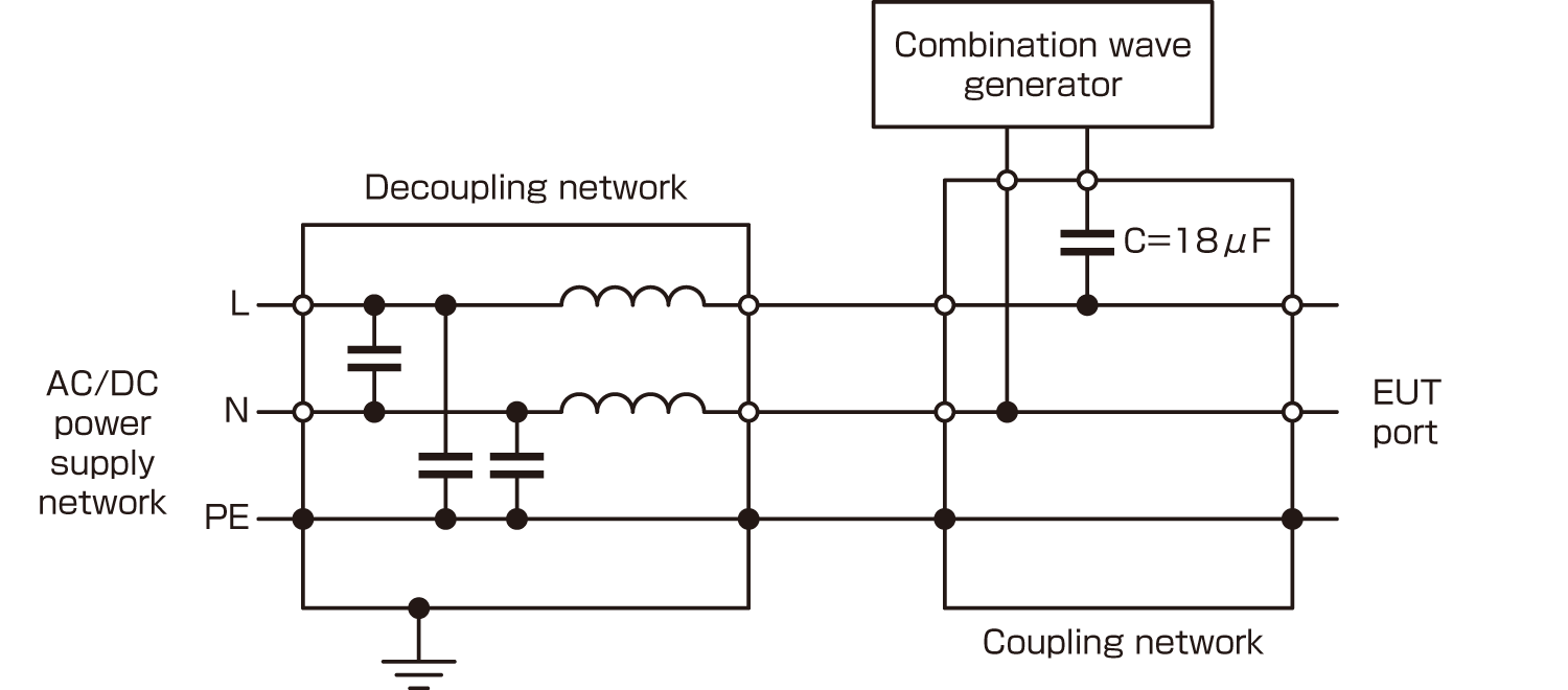
Single phase power line CDN (line-to-line mode)

■ Single phase power line CDN (line-to-ground mode)
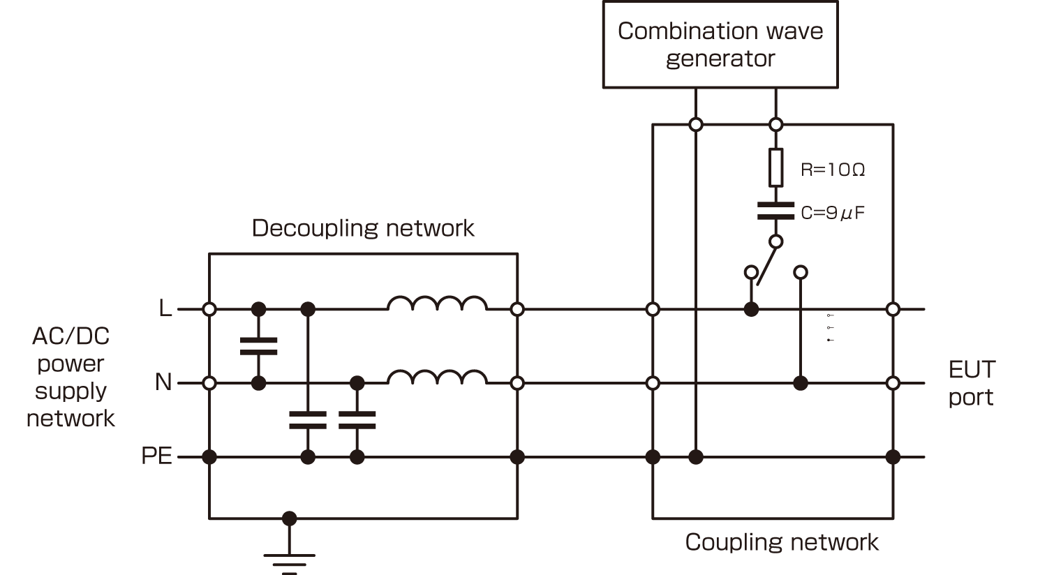
Single phase power line CDN (line-to-ground mode)

■ Three-phase power line CDN (line-to-line mode)
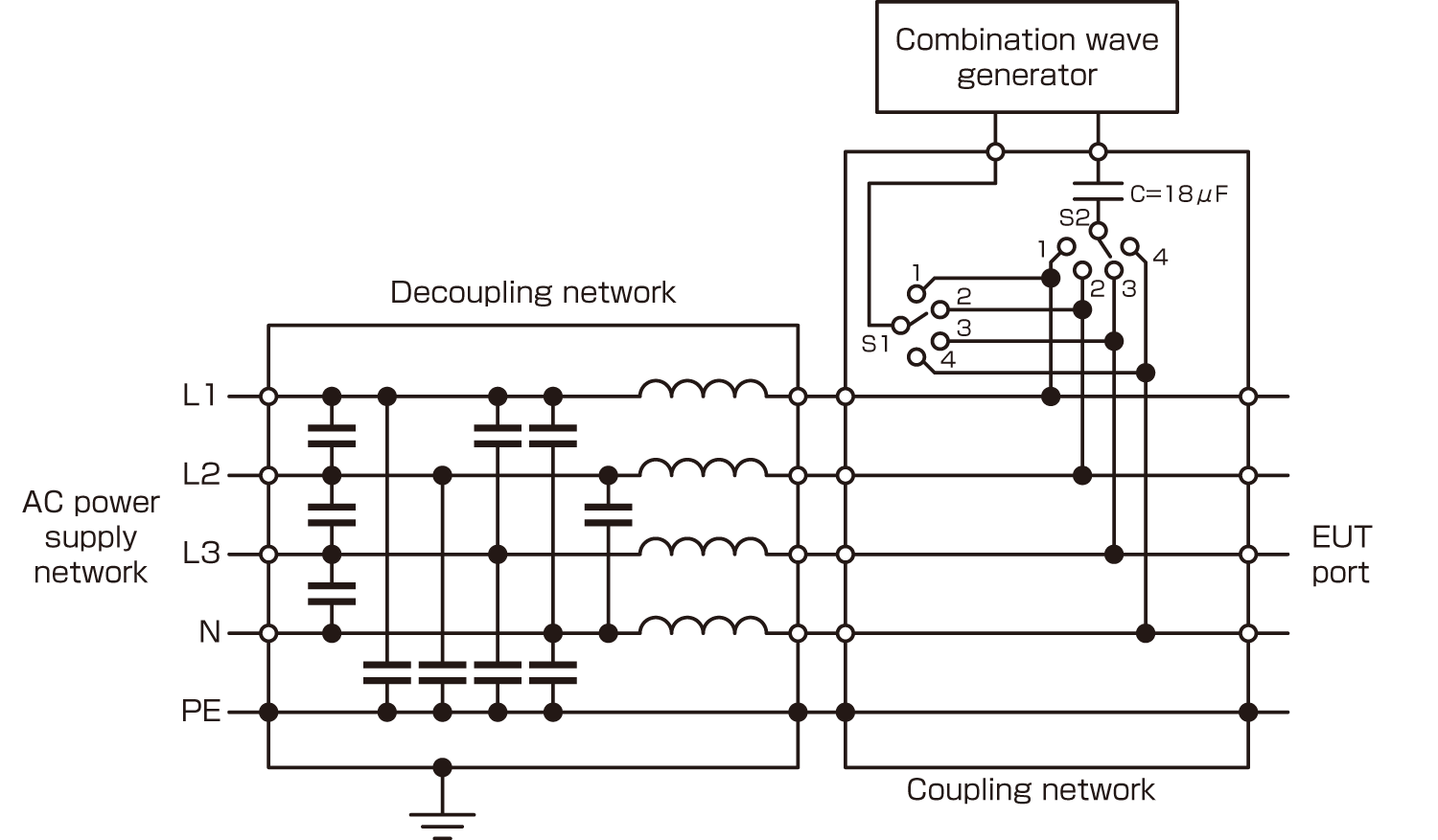
Three-phase power line CDN (line-to-line mode)

■ Three-phase power line CDN (line-to-ground mode)
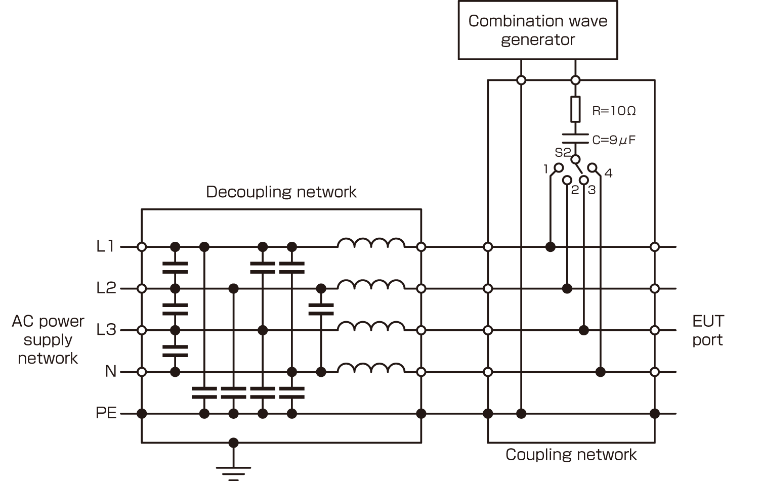
Three-phase power line CDN (line-to-ground mode)

■ CDN for unshielded unsymmetrical interconnection lines
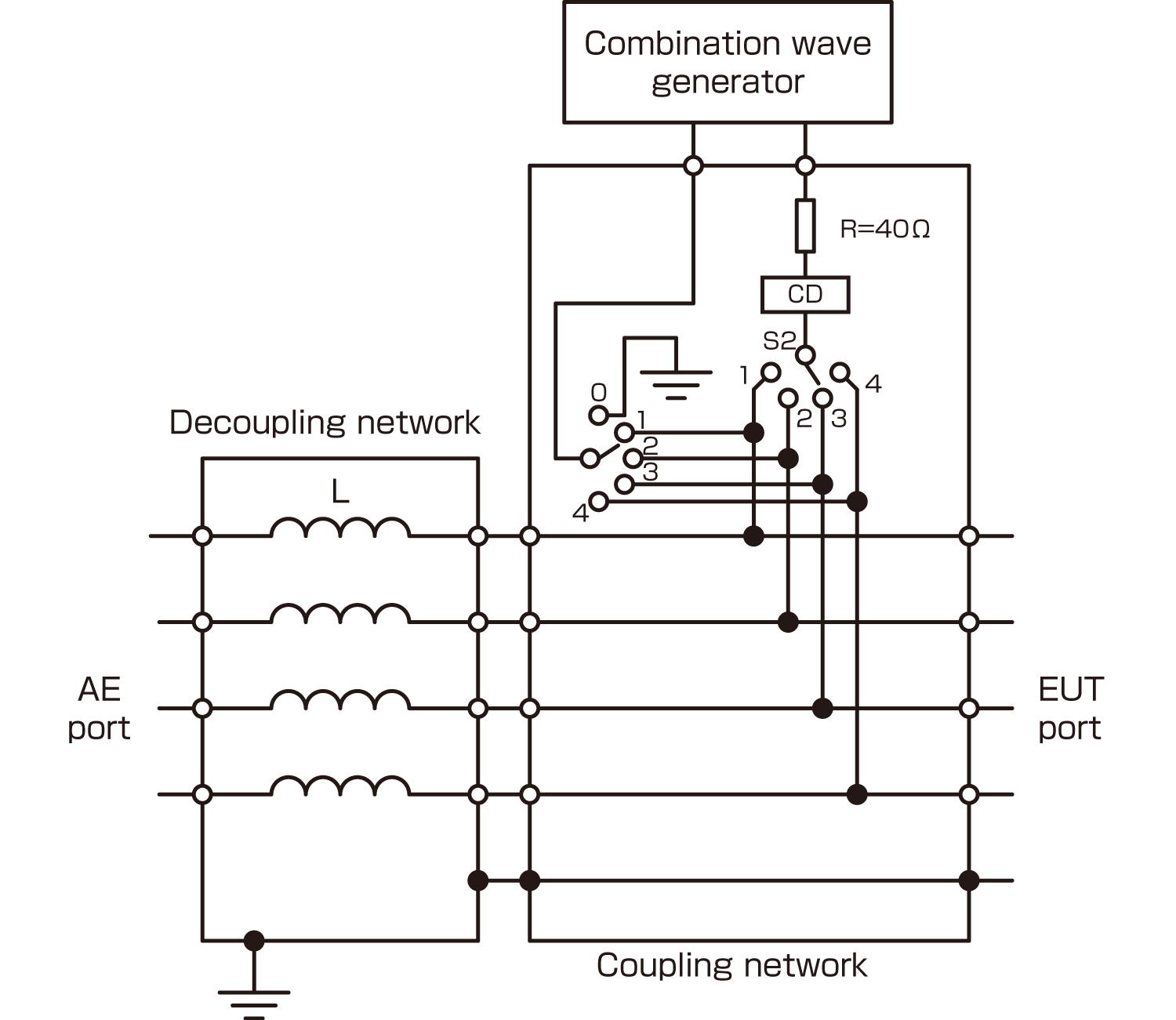
CDN for unshielded unsymmetrical interconnection lines

■ CDN for unshielded symmetrical interconnection lines
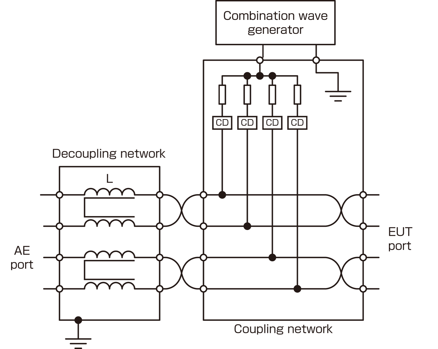
CDN for unshielded symmetrical interconnection lines

■ CDN for unshielded symmetrical high speed communication lines up to 1000Mbit/s
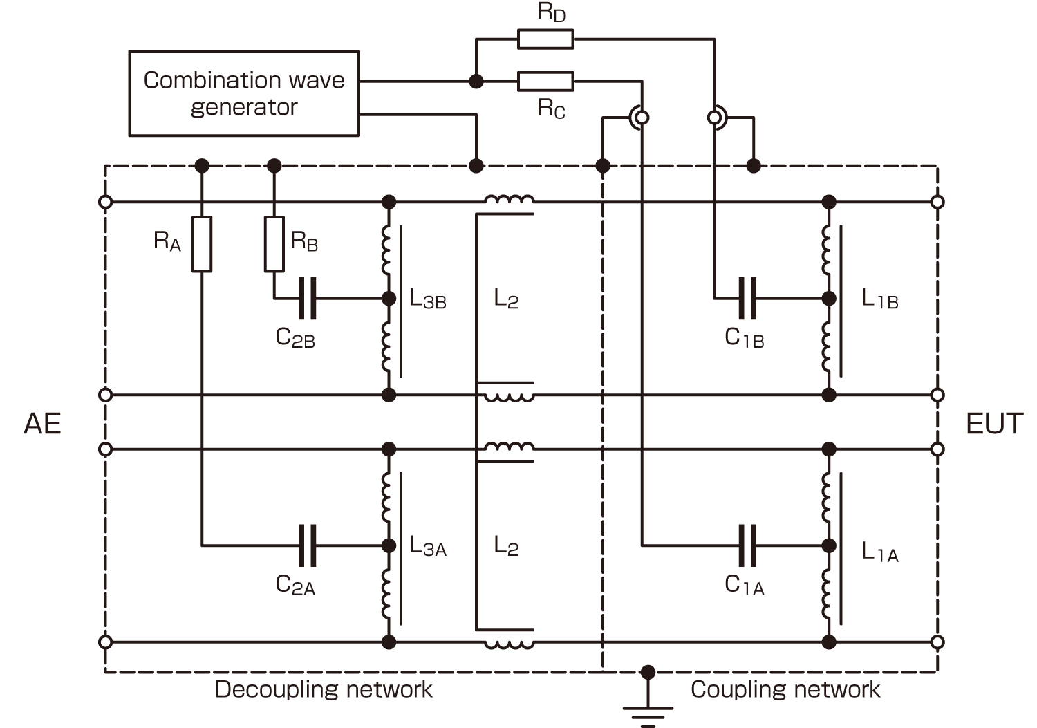
CDN for unshielded symmetrical high speed communication lines up to 1000Mbit/s

■ Surge waveform specifications at the EUT port of the CDN for unshielded unsymmetrical interconnection lines

Coupling methodOutput voltage from the generatorOpen-circuit Voltage at the EUT port of the CDN Voc ±10 %Voltage front time Tf = 1,67 ×Tr ±30 %Voltage duration Td = Tw ±30 %Short-circuit current at the EUT port of the CDN Isc ±20 %Current front time Tf=1,25xTr ±30 %Current Duration Td=1,18xTw ±30 %
Line to PE R = 40Ω, CD = 0,5 µF4 kV4 kV1,2 µs38 µs87 A1,3 µs13 µs
Line to PE R = 40Ω, CD = GDT4 kV4 kV1,2 µs42 µs95 A1,5 µs48 µs
Line-to-line R = 40Ω, CD = 0,5 µF4 kV4 kV1,2 µs42 µs87 A1,3 µs13 µs
Line-to-line R = 40 Ω, CD = GDT4 kV4 kV1,2 µs47 µs95 A1,5 µs48 µs

■ Surge waveform specifications at the EUT port of the CDN for unshielded symmetrical interconnection lines

Coupling methodOutput voltageOpen-circuit Voltage at the EUT port of the CDN Voc ±10 %Voltage front time Tf = 1,67 xTr ±30 %Voltage duration Td = Tw ±30 %Short-circuit current at the EUT port of the CDN Isc ±20 %Current front time Tf=1,25xTr ±30 %Current Duration Td=1,18xTw ±30 %
Line to PE R = 40Ω Coupling devices*2 kV2 kV1,2 µs45 µs48 A1,5 µs45 µs

* GDT, Clamping device, Avalanche devices

It is recommended that the CDN calibrated at the highest rated voltage. The values shown in the table are for a set value of 4 kV. If the CDN is rated for another maximum voltage, the calibration shall be performed at that maximum voltage. (In case the maximum voltage is 6kV, multiply the short circuit current value shown in this table by 1.5.)

5. Test Setup

■ Application of surges to power supply lines
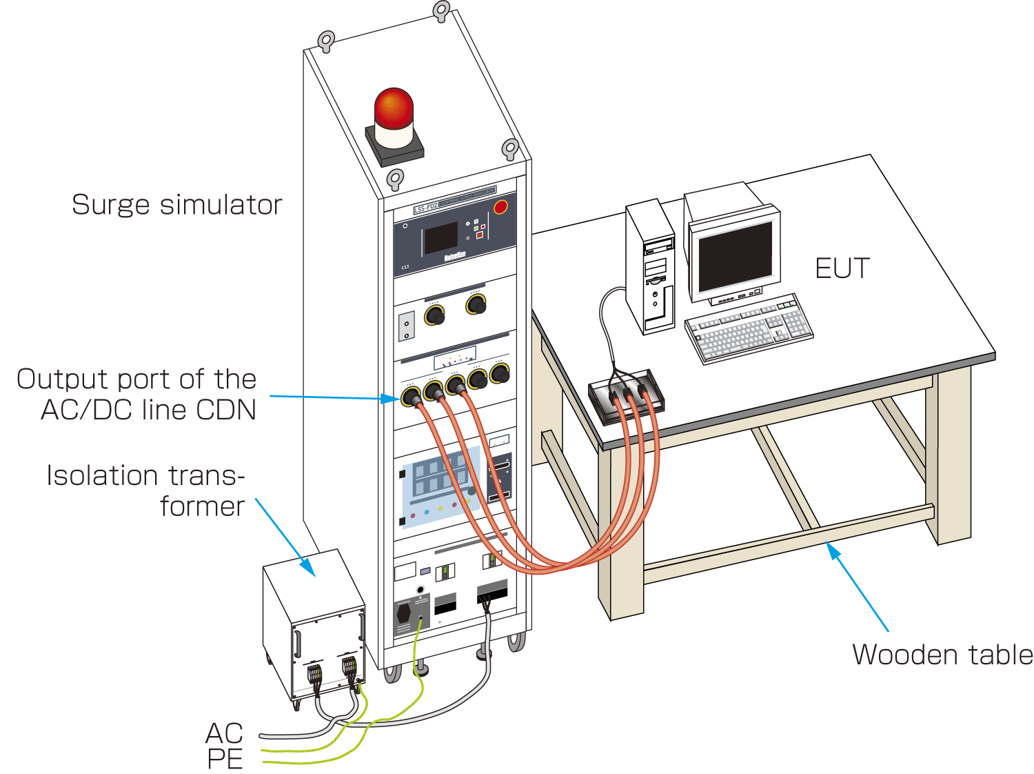
Application of surges to power supply lines

The 1.2/50 combination wave specified in the IEC61000-4-5 standard is applied from Lightning Surge simulator’s CDN to power supply of the EUT. Compliant with the standard requirements, the simulator is equipped with a floating output. The simulator can conduct a series of automated tests based on preprogrammed settings.

■ Application of surges to telecom lines
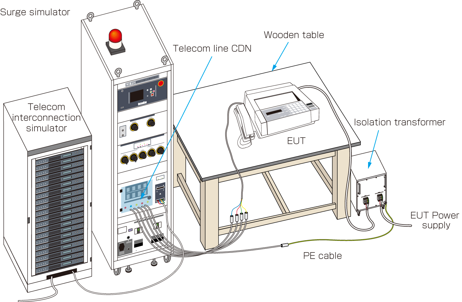
Application of surges to telecom lines

The 1.2/50 combination wave surge specified in IEC 61000-4-5 Standard is applied to the telephone line of an EUT(such as a facsimile machine) through a high-speed telecom CDN connected to Lightning Surge simulator.

■ Application of surges through unshielded

unsymmetrical interconnection lines CDN

The 1.2/50μs surge generator of the LSS-F03 simulator shall be used in combination with an optional external CDN. This CDN is connected between the EUT and AE (auxiliary equipment).

For all tests shown here, if it is not otherwise specified, the length of cable between the EUT and CDN should not exceed 2m.
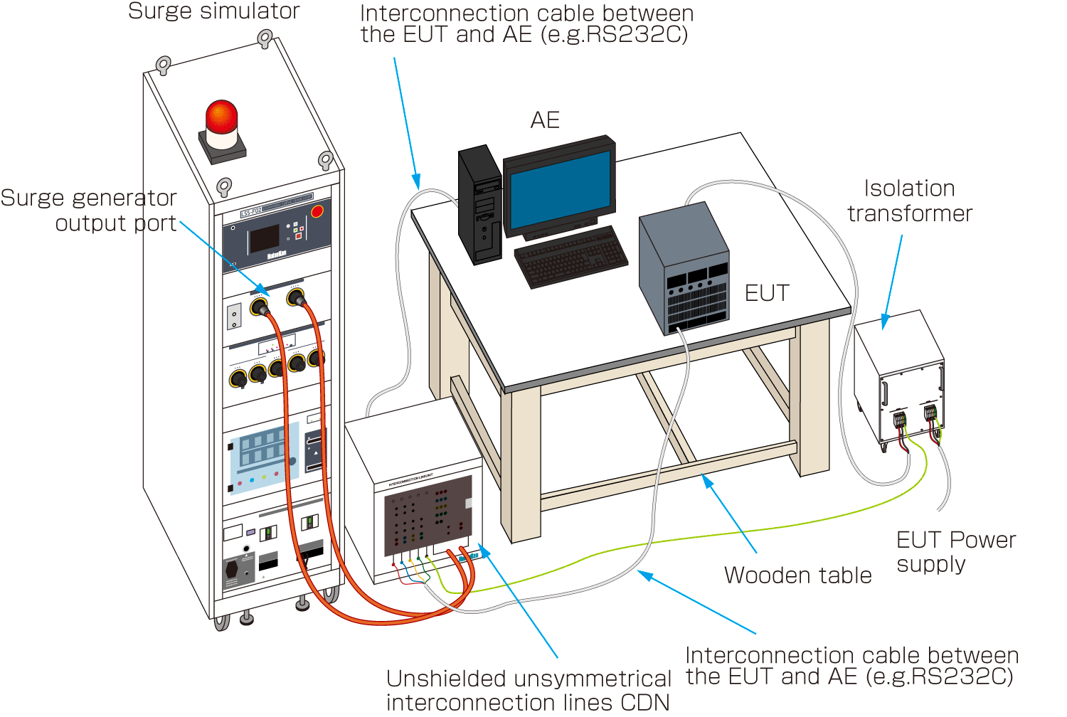
Application of surges through unshielded unsymmetrical interconnection lines CDN

■ Application of surges to shielded lines

In case of shielded lines, the surge shall be applied to the metallic enclosure of the EUT (for the EUT without a metallic enclosure, the surge shall be applied to the shields of the cable).
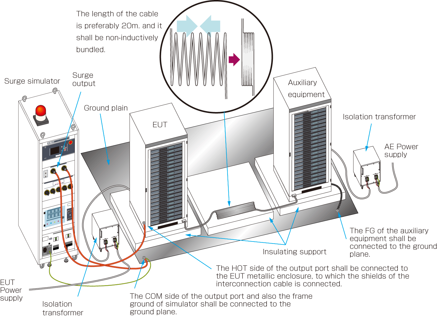
Application of surges to shielded lines

Application of the surges shall be done from the generator output port via a 18μF capacitor. The auxiliary equipment shall be connected to the ground plane while the EUT shall not.
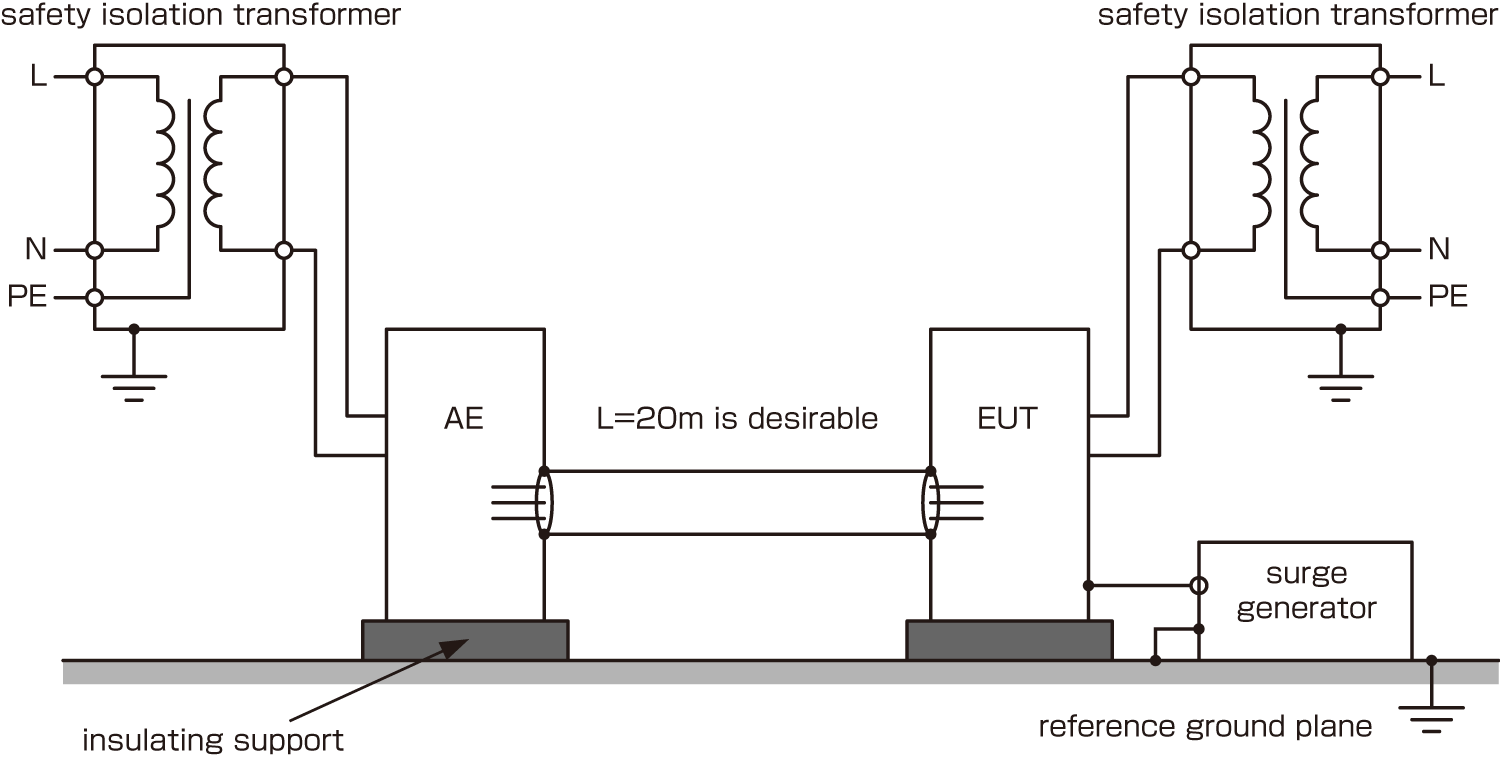
The above test layouts is an example of a setup using our lightning surge tester. There are no regulations regarding test layout in the IEC Standard.

6. Test procedure

■ Execution of the test

・Number of surges

For DC power ports and interconnection lines five positive and five negative surge pulses.

For AC power ports five positive and five negative pulses each at 0º, 90º, 180º and at 270º;

・Time between successive pulses: 1 min or less

7. Evaluation of Test Results and Test Report

The test results shall be classified in terms of the loss of function or degradation of performance of the equipment under test, relative to a performance level defined by its manufacturer or the requestor of the test, or agreed between the manufacturer and the purchaser of the product. The recommended classification is as follows:

1) Normal performance within limits specified by the manufacturer, requestor or purchaser;

2) Temporary loss of function or degradation of performance which ceases after the disturbance ceases, and from which the equipment under test recovers its normal performance, without operator intervention;

3) Temporary loss of function or degradation of performance, the correction of which requires operator intervention;

4) Loss of function or degradation of performance which is not recoverable, owing to damage to hardware or software, or loss of data.

Generally, as far as the EUT can be immune to the surges injected during all injection period and it satisfies the functional requirements according to the product specification, the test result can be judged as “Good”.

The test report shall contain the test conditions and the result.

Note: These test setups and procedures are quoted from IEC61000-4-5 Ed.3 (2014) Standard. Please refer to the standard if more details are required.

8. Surge testing for unshielded outdoor symmetrical communication lines

The 3rd edition of the standard requires the 10/700 us combination wave to be applied to ports connected to outdoor telecommunication lines only and the Annex A (Normative) dedicatedly address this test. Outdoor telecommunication lines are typically greater than 300m in length, as the result of this length 10/700μs wave is more representative. Telecommunication lines are usually protected by a primary protector installed at the cable entry to building. Testing shall be performed including the intended primary protector.

■ 10/700 combination waveform (10/700・5/320μs) generation circuit
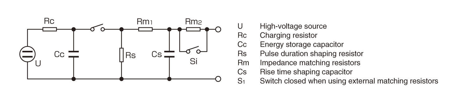
10/700 combination waveform (10/700・5/320μs) generation circuit

■ Open circuit voltage waveform
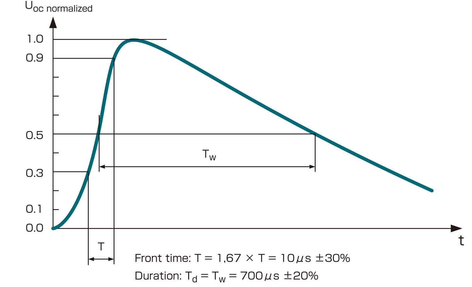
Open circuit voltage waveform

■Short circuit current waveform
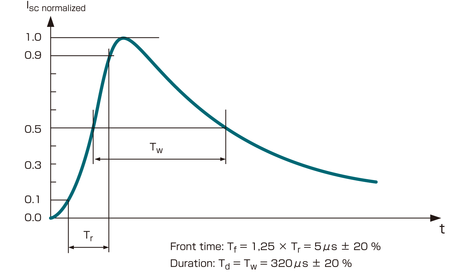
Short circuit current waveform

■ Definitions of the waveform parameters of 10/700 μs combination waveform

Front time µsDuration µs
Open-circuit voltage10 ± 30 %700 ± 20 %
Short-circuit current5 ± 20 %320 ± 20 %

■ Relationship between peak open-circuit voltage and peak short-circuit current of the 10/700μscombination waveform

Peak open-circuit voltage at generator output ±10 %Peak short-circuit current at generator output ±10 %
0,5 kV12,5 A
1,0 kV25A
2,0 kV50A
4,0 kV100A

■ Test setup example for 10/700 μs generator and CDN for outdoor unshielded symmetrical communications lines
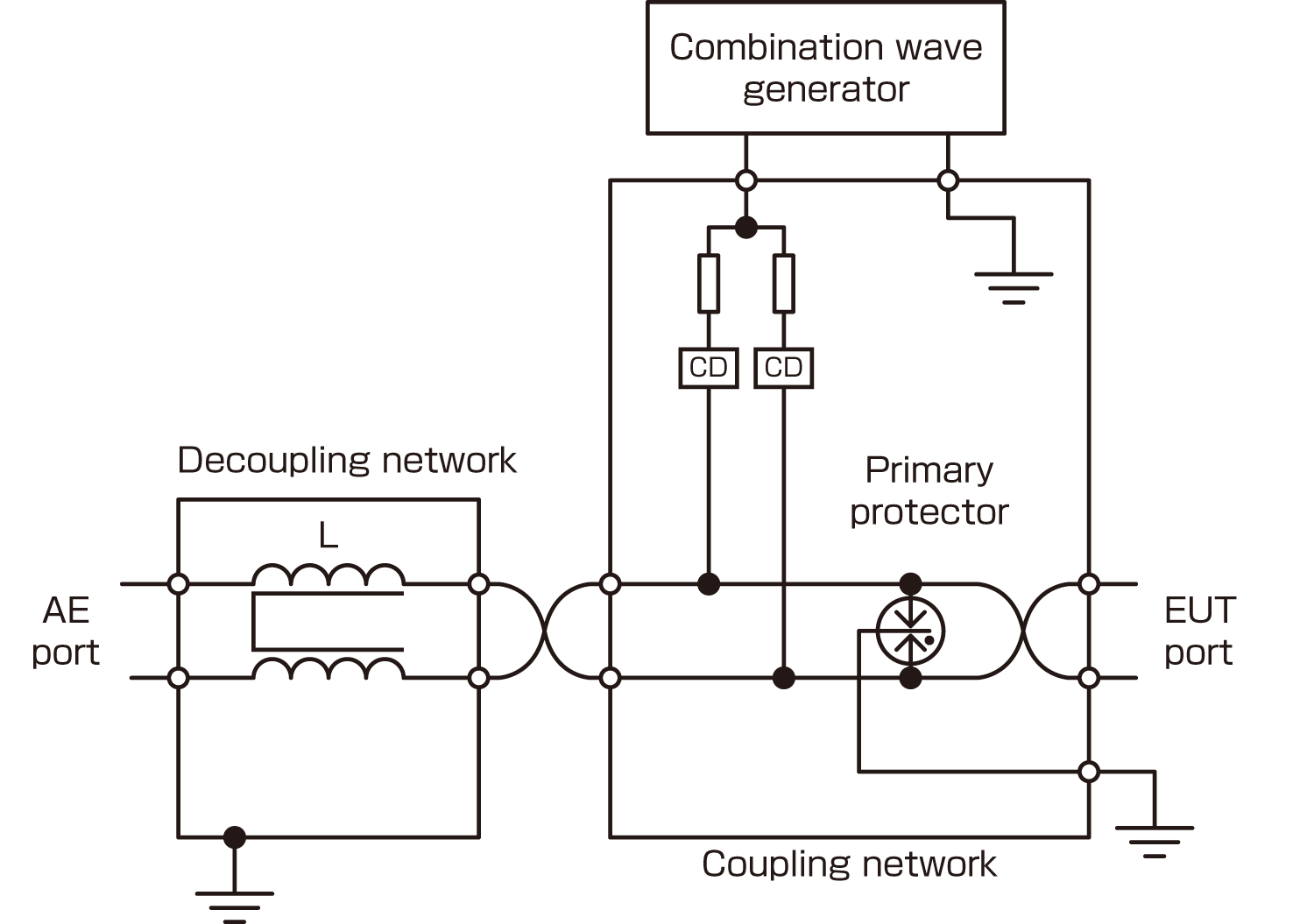
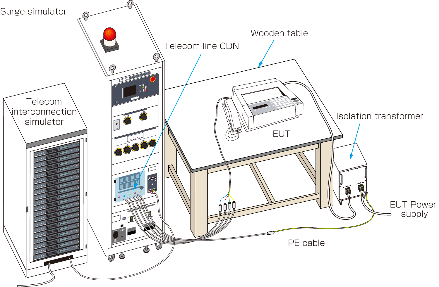
Test setup example for 10/700 μs generator and CDN for outdoor unshielded symmetrical communications lines

■ Surge waveform specifications at the EUT port of the CDN for unshielded outdoor symmetricalcommunication lines

Coupling methodOutput voltage from the generatorOpen-circuit voltage at the EUT port of the CDN Voc ±10 %Voltage front time Tf = 1,67 xTr ±30 %Voltage duration Td = Tw ±30 %Short-circuit current at the EUT port of the CDN Isc ±20 %Current front time Tf ±30 %Current duration Td ±30 %
Common mode Coupling devices 1 pair 27,5 Ω4 kV4 kV8 µs250 µs145 A3,2 µs250µs

Note: These test setups and procedures are quoted from IEC61000-4-5 Ed.3 (2014) Standard. Please refer to the standard if the more details are required.

Shinyei Corporation of America is the sole authorized distributor of NoiseKen products. We offer the most direct sales of NoiseKen products available in the US.

PRODUCTS

  • WEATHERING, CORROSION, AND OPTICAL PROPERTIES
    • Products
    • Weather Meters
      • Super Xenon Weather Meters
      • Xenon Weather Meters
      • Metaling Weather Meters
      • Sunshine Weather Meters
      • Fluorescent Weather Meter FUV
      • UV Fade Meters
      • LED Fade Meters
      • Spectral Radiation Tester SPX
    • Light Sources
      • 7.5kW Xenon lamp & Sunlight
      • 3kW Metaling Lamp
      • Sunshine Carbon Arc
      • UV Fluorescent Lamp
      • UV Carbon Arc
    • Corrosion Test Chambers
      • Salt Spray Test Chambers
      • CASS Test Chambers
      • Combined Cyclic(CYP)
      • Combined Cyclic(CCT)
      • Custom Test Chambers
      • Options for Corrosion Test Chambers
    • Other Test Chambers
      • Gas Corrosion Test Chambers
      • Ozone Weather Meters
      • Fogging Testers
      • Dust Test Equipment
      • Rain Test Equipment
      • Gravel Test Equipment
      • Abrasion Test Equipment
      • Flammability Test Chambers
    • Optical Property Meters
      • Color Meters
      • Gloss Meters
      • Haze Meters
        • HZ-V3(DISCONTINUED)
        • HZ-V4 (NEW)
      • Image Clarity Meters
      • Reflectance /
        Transmittance Meters and Others
  • EMC EMISSION & IMMUNITY
    • Products
    • ESD Gun
      • Battery Unit and ESD gun (ESS-PS1+GT-31S) per IEC 61000-4-2 Ed.2/Ed.3 Test Standard
      • (NEW)ESD Simulator and Gun (ESS-S3011A+GT-30RB) per IEC 61000-4-2 Ed.2/Ed.3 Test Standard (GT-30RA is discontinued.)
      • Battery Unit and ESD gun (ESS-PS1+GT-31S+GT-ISOSET-A) per ISO 10605 Ed.2/Ed.3 Test Standard
      • (NEW)ESD Simulator and Gun (ESS-S3011A+GT-30R3302KB) per ISO 10605 Ed.2/Ed.3 Test Standard(Availability of ESS-S3011A+GT-30R3302KA per ISO 10605 Ed.2: please contact us.)
    • ESD voltage meter (New)
    • Fast Transient Burst Simulators
    • Impulse Noise Simulator
      (for 2kV and 4kV)
    • Impulse Noise Simulator (New)
      (for 50V to 1kV)
    • Lightning Surge Simulator
      • Lightning Surge Simulator LSS-FE01 Series
      • Lightning Surge Simulator LSS-F03 Series
      • Lightning Surge Simulator LSS-720B2
      • Lightning Surge Simulator(RINGWAVE generator equipped)
      • Lightning Surge Simulator (AC690V/100A) (AC600V/200A,DC1000V/200A) (DC1000V/63A)
    • New ISO 7637 Standard Automotive Transient Surge Simulator
    • High Voltage Noise
    • Field Decay Load Dump
    • TEM Horn Antenna
    • Broadband Sleeve Antenna
    • Electromagnetic Field Visualization System
  • DROP & SHOCK
    • Products
    • Drop Test Systems
      • DT-202AIR
      • DT-202 series
      • DT-205 series
      • DT-20e
      • RDT-1000
      • EMH series
    • Shock Test Systems
      • PDST series
      • HDST series
      • ASQ series
      • MDST series
      • SDST series
      • PST-300
      • CDS series
      • Accessories
    • Material Testing System
      • ACST series
    • Acceleration Measurement
      • SM-500
      • AccStick
    • Field Data Recorder
      • DER-1000
  • VIBRATION
    • Products
    • Basics of Vibration Testing
    • Multi-Axis Vibration Test Systems
    • Single-Axis Vibration Test Systems
    • Vibration Combined Environmental Test Systems
    • Digital Vibration Controller
  • BALL BEARINGS
    • Products
    • Stainless Steel Ball bearing by AFC bearings
    • AISI 440C Stainless Steel Ball Bearings
    • AISI 304 Stainless Steel Ball Bearings
    • AISI 630 Stainless Steel Ball Bearings
    • 2C Series - Ceramic Bearings
    • Grease Free Bearings
    • 1T Series - Pure Titanium Bearings
    • SH series - Stainless Ball Bearing with Aligning Ring
    • SSXC Series - Stainless steel ball bearings with setscrews
    • SF series - AISI440C Flanged Bearing Units
  • MECHANICAL & PHYSICAL
    PROPERTY OF MATERIALS
    • Products
    • By Test Applications
      • Plastic / Resin / Rubber
    • By Test Properties
  • TEMPERATURE SENSING
    • Products
    • Temperature Probes
      • Stationary Surface Temperature Probes
        • SX Series
        • AX Series
        • WE Series
      • Moving/Rotating Surface Temperature Probes
        • U Series
      • Moving Wire / Tube Probe
      • Liquid / Semiliquid Probes (Needle type)
      • Special Application Temperature Probes
        • AW Series(for Wafer)
    • Thermometers
      • Handheld Thermometer Model HR series
      • Handheld Thermometer
      • Thermoprinter
      • Thermologger
        • Thermologger AM-8000
        • Thermologger AM-9000
      • Transducer (Transmitter) HPD Series
      • Non-contact thermometer
      • Soldering iron thermometer
      • Fiber optic thermometer
    • Application
    • Accessories
    • Technical Guide
    • FAQ
  • ENERGY DISPERSIVE X-RAY FLUORESCENCE ANALYZERS
    • Products
    • VoXER
    • OURSTEX 170
    • OURSTEX 101FA
    • OURSTEX 100FA
    • OURSTEX 100TA-F
    • OURSTEX 200TX
    • OURSTEX 160
    • OURSTEX 160RoHS
    • OURSTEX 160M
  • NO-DOOR ENVIRONMENTAL CHAMBERS
    • LST Series
  • ENVIRONMENTAL &
    THERMAL SHOCK CHAMBERS
    • Products
    • Temperature and Humidity
    • Thermal Shock
    • Compact Temperature and Humidity
  • HUMIDITY, PARTICLE, AND
    GAS SENSING
    • Products
    • Humidity Sensing
      • humidity Sensors
      • humidity and Temperature
      • Thermo-hygrometer/Recorder
      • Temperature humidity converter
      • TDLAS Moisture Analyzers
      • Humidity Generators
    • Particle Sensing
      • Particle Sensor Unit
      • Particle Sensing Monitor
      • Pollen Sensor
    • IAQ Sensing
      • Handheld Odor Meter
  • CONTRACT TEST SERVICE

  • SUGA
  • NOISEKEN
  • SHINYEI
  • VIBRATION
  • BALL BEARING
  • YASUDA
  • ANRITSU
  • OURSTEX
  • ETAC
sca Shinyei Corporation of America

Head Office
1120 Avenue of the Americas,
4th Floor NewYork, NY 10036
TEL:917-484-7884 / FAX: 212-704-4206

CONTACT US
sca Shinyei Corporation of America

Mexico Liaison Office
Blvd. Bernardo Quintana No.7001,
Q7001 Torre 1 - Int. 808,
Col. Centro Sur, C.P. 76090,
Queretaro, QRO, Mexico
TEL:442-229-0767

CONTACT US
© 2018 Shinyei Corp. of America All rights reserved.