Basics of Vibration Testing
What is the Vibration Test?
- The Vibration Durability Test is used to ensure that newly designed products can survive in use during their lifespan and operate satisfactorily against any vibration stress, thus inevitably required to win over the tough market.
Purposes of the Vibration Test

-
01. Vibration Durability Tests
For Parts for Automobiles, Electronic Devices, Airplanes etc.To ensure that newly designed products can survive in use during their lifespan and operate satisfactorily against any vibration stress

-
02. Transportation Tests
For Home Electric Appliances, OA Apparatus etc.To ensure that products, to be shipped, can survive during transportation against any vibration stress, including their package

-
03. Stress Screening in Production Line
At Various Hardware Assembly LevelsTo check on parts/workmanship failures at module, unit and system levels; the lower the assembly level, the fewer total failure

-
04. Anti-Earthquake Measures
For Construction, Gas Heater, Oil Stoves etc.Vibration Research to prevent or minimize damage/destruction/performance trouble on constructions, equipment etc. by earthquakes

-
05. Calibration of Vibration Meters and Seismometers
Calibration & Performance Check of Vibration Meters, Seismometers etc.

-
06. Vibration Analysis and Measurement
For Vehicles, Vessels, Trains, Construction, Metal etc.Fundamental tests for designing by measurements of vibration response on parts, material, structure etc. and mechanical impedance

-
07. Production Process Assistance
Fling up Churning of Industrial Powders & Fluids etc.
Calculation of Force Output
In order to select the optimum model for a given application, it is necessary to calculate how much force will be generated in a given test. The following equation is used to calculate the force.
F=(m0+M1+M2)A- F : Force Output〔N〕
- A : Acceleration〔m/s2〕
- m0: Weight of Bare Table〔kg〕
- M1: Weight of Aux. Table and/or Fixture if any〔kg〕
- M2 : Weight of Specimen〔kg〕
When the test acceleration is unknown, the following formula can be used instead. (Only for Sine tests)
A=2πfVA=(2πf)2D
- f : Frequency〔Hz〕
- V : Velocity〔m/s〕
- D : Displacement〔mo-p〕
- A : Acceleration〔m/s2〕
SI Units
The following table is a conversion table from the conventional units to the SI Units
| Quantity | Conventional Unit | SI Unit | Conversion Rate |
| Force | kgf | N | 1 kgf=9.8 N |
| Acceleration | G | m/s² | 1G=9.8 m/s² |
| Velocity | cm/s | m/s | 1 cm/s=0.01 m/s |
| Frequency | Hz | Hz | |
| Moment | kgf・m | N・m | 1 kgf・m=9.8 N・m |
| Pressure | kgf/cm² | Pa | 1 kgf/cm² =98 kPa |
| Outflow Volume | L/min | m³/s | L/min=(10-3/ 60) m³/sec |
| Heat Volume | kcal | J | 1 kcal=4.186 kJ |
| Radiation Heat Volume | kcal/h | W | 1 kcal/h=1.162 W |
| Angle | °(degree) | rad | 1°=π・rad/180 |
3 Mechanism Types of the Vibration Test Systems
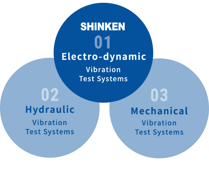
Electro-Dynamic Vibration Test Systems
cost-effective systems that SHINKEN uses.
Mechanical Vibration Test Systems
Usable only for simple "far-from-real-world-vibration" sine tests, have almost become extinct as "more-realistic-real-world-vibration" random tests have become more popular.
Hydraulic Vibration Test Systems
Featured by large force, are usually slightly less expensive than the Electro-dynamic Vibration Test Systems as far as larger systems than 50kN with large vibration tables are concerned, while the running cost including the maintenance cost for the Hydraulic Systems is far higher with a lot of oil being used. Also the hydraulic power supply system used for the Hydraulic Systems caused a high noise problem. In addition, the usable upper frequency of the Hydraulic Systems is said to be much lower than that of the Electro-dynamic Systems at about 200Hz as well as to be less controllable due to slow oil response against input control signals.
Principle of the Electro-Dynamic Vibration Generators

"Fleming's Left-hand Rule", the electromagnetic effect that when an electric current is applied to a conductor in a magnetic field, the conductor receives a force’ is widely applied to various devices such as motors, peakers and meter instruments including Electro-dynamic Vibration Generators. Its principle is as follows: There is a gap in the cylindrical magnetic path as shown in the right drawing and the driving coil being supported with the spring is inserted in the gap. When a direct current is supplied to the field coil in the magnetic path, the magnetic flux is generated in the direction of the arrows shown in the drawing and the DC magnetic field is produced in the gap. Then by applying an alternating current to the driving coil, the driving coil is being moved up and down, which is called "Vibration". The generated force is proportional to the alternating current level to be applied.
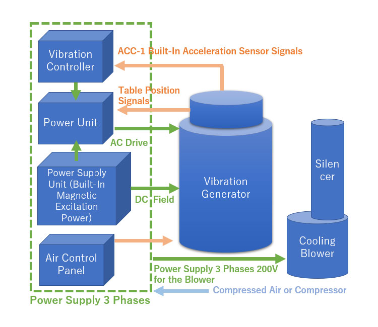
The structure of the actual Electro-dynamic Vibration Generators is very complicated with a variety of specially-designed parts and components being built in to improve the magnetic flux efficiency of the above-mentioned field coil(s) and also to maintain stable long-time operation with the Electro-dynamic Vibration Generators featured by the wide frequency range and high acceleration being capable of easily generating the required amount of vibration in the designated time-domain waveform or frequency-domain pattern simply controlling the current. The typical Block Diagram of the Electro-dynamic Vibration Test System is shown on the left side. This is the basic configuration and other devices are to be added depending upon the test conditions and usage.
Vibration Test System Configurations
The Vibration Test System is basically configured with Vibration Generator, Cooling Device, Power Amplifier and Vibration Controller. With other device(s) optionally available being added, vibration tests can be carried out to meet a variety of vibration test purposes.
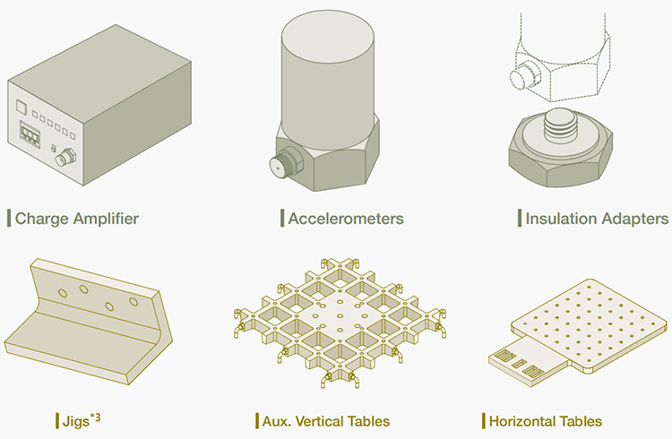
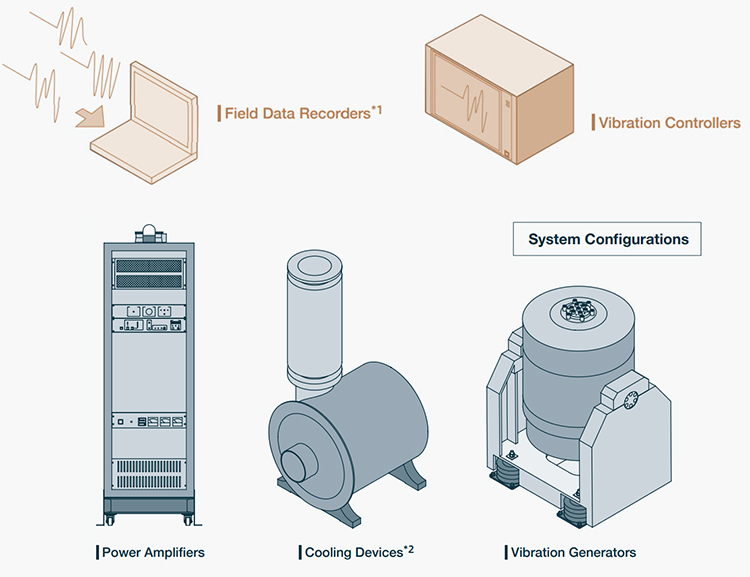
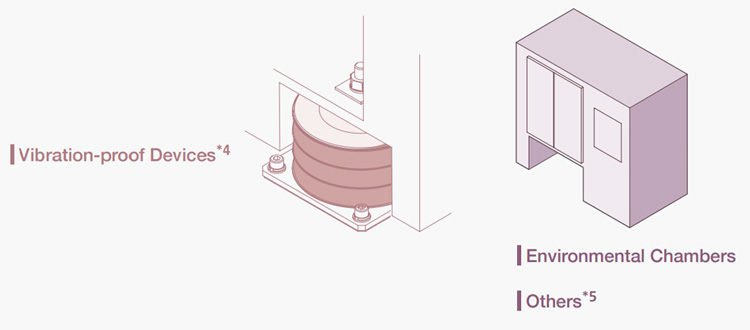
- *1 Field Data Recorders: For recording environmental field data (Acceleration, Temperature and Humidity). The recorded data (in CSV format) can be imported into the Vibration Controller.
- *2 Cooling Devices: For cooling down the Vibration Generator
・Cooling Blower with Silencer 〈Air-cooled〉/ Heat Exchanger 〈Water-cooled〉 - *3 Jigs: Please contact us for advice & design for and manufacturing of Jigs suited for your Product.
- *4 Vibration-proof Devices: For reducing vibration leaked from the Vibration Generator to be transmitted to the floor.
・Pneumatic Isolators / Foundation Setting - *5 Others: Please contact us about combined tests with the following equipment.
・Oven / Gas Burner / Centrifugal Machine / Sound-Proof Box / Explosion-Proof Enclosure
Test Standard Examples
| Test Standards | Contents |
|---|---|
| IEC 60068-1 (=JIS C 60068-2-6) | Environmental testing -- Part 2-6: Tests – Test Fc: Vibration (sinusoidal) |
| IEC 61960 (=JIS C 8713) | Secondary cells and batteries containing alkaline or other non-acid electrolytes -- Mechanical tests for sealed portable secondary cells and batteries |
| JIS D 1601 | Vibration testing methods for automobile parts |
| ISO/IEC-16750-3 (=JASO D 014-3) | Road vehicles — Environmental conditions and testing for electrical and electronic equipment |
| ISO8318:2000,13355:2016 (= JIS Z 0232) | Packaged freights -- Method of vibration test |
| ISTA | International Safe Transit Association: Performance Tests for Packaged-Products |
| ASTM D4169 | American Society for Testing and Materials Standards: Standard Practice for Performance Testing of Shipping Containers and Systems |
| IEC61373 (=JIS E 4031) | Rolling stock equipment -- Vibration and shock tests |
| IEC 60529 (=JIS F 8006) | General requirements for vibration test of electrical apparatus for marine use |
| ISO 2685 (=JIS W 0812) | Airborne equipment -- Environmental conditions and test Procedures |
| JIS S 1018 | Test methods of vibration and earthquake tumbling for furniture |
| UN38.3 | United Nations Lithium Battery Testing Requirements |
| JEDEC Standard JESD22-B103-B | Vibration, Variable Frequency |
| NEBS(Network Equipment Building System) GR-63-CORE | Seismic qualified enclosures for telecommunications equipment and components |
