ESD simulator ISO 10605 Ed.3 Test Standard
Shinyei Corporation of America is the sole authorized distributor of NoiseKen products. We offer the most direct sales of NoiseKen products available in the US.
General
Electrostatic discharges which are generated both in vehicles and while we get on and off there can be factors to cause malfunction of the electrical devices and components. Nowadays, more attention has been paid, as vehicles install more and more electronic devices and components. This Standard provides that static electricity is discharged to the electronic devices or equipment from the charged human body and tests are simulated by electrical circuit to reproduce the electric current waveform at the discharge.
In addition to procedures for the immunity tests and evaluations in state that the electronic devices or equipment work while the vehicle is driving, also, the Standard provides tests procedures to evaluate the immunity of the each module against simulated human discharges during the assembly process or in servicing.
Test Levels
The following tests levels are reference. The categories are classified according to functional importance of the electronics devices/components.
Component test – Example severity levels for direct contact discharge and direct air discharge (Function performance status)
| Direct contact discharge | Direct air discharge | |||||
| Test severity level | Category 1 | Category 2 | Category 3 | Category 1 | Category 2 | Category 3 |
| Level 4 | ±8kV | ±8kV | ±15kV | ±15kV | ±15kV | ±25kV |
| Level 3 | ±6kV | ±8kV | ±8kV | ±8kV | ±8kV | ±15kV |
| Level 2 | ±4kV | ±4kV | ±6kV | ±4kV | ±6kV | ±8kV |
| Level 1 | ±2kV | ±2kV | ±4kV | ±2kV | ±2kV | ±6kV |
Component test – Example severity levels for indirect contact discharge (Function performance status)
| Direct contact discharge | |||
| Test severity level | Category 1 | Category 2 | Category 3 |
| Level 4 | ±8kV | ±15kV | ±20kV |
| Level 3 | ±6kV | ±8kV | ±15kV |
| Level 2 | ±4kV | ±4kV | ±8kV |
| Level 1 | ±2kV | ±2kV | ±4kV |
Component test — Packaging and handling — Example severity levels —
| Direct contact discharge | Direct air discharge | |||||
| Test severity level | Category 1 | Category 2 | Category 3 | Category 1 | Category 2 | Category 3 |
| Full function after test | ±1kV | ±2kV | ±4kV | ±8kV | ±15kV | ±25kV |
Vehicle test — Example severity levels for contact discharge and air discharge (Test points accessible only from inside vehicle)
| Contacts discharge | Air discharge | |||||
| Test severity level | Category 1 | Category 2 | Category 3 | Category 1 | Category 2 | Category 3 |
| Level 4 | ±6kV | ±8kV | ±8kV | ±8kV | ±15kV | ±15kV |
| Level 3 | ±4kV | ±4kV | ±6kV | ±6kV | ±8kV | ±8kV |
| Level 2 | ±2kV | ±2kV | ±2kV | ±4kV | ±4kV | ±6kV |
| Level 1 | - | - | - | ±2kV | ±2kV | ±4kV |
Vehicle test — Example severity levels for contact discharge and air discharge (Test points accessible only from outside vehicle)
| Contacts discharge | Air discharge | |||||
| Test severity level | Category 1 | Category 2 | Category 3 | Category 1 | Category 2 | Category 3 |
| Level 4 | ±6kV | ±8kV | ±8kV | ±15kV | ±15kV | ±25kV |
| Level 3 | ±4kV | ±6kV | ±6kV | ±8kV | ±8kV | ±15kV |
| Level 2 | ±2kV | ±4kV | ±4kV | ±4kV | ±6kV | ±8kV |
| Level 1 | - | - | ±2kV | ±2kV | ±4kV | ±6kV |
Specification of generator and verification of output waveform
SPECIFICATION OF ESD SIMULATOR
Following specification must be satisfied with the simulator for the test.
| Output voltage . Contact discharge-(kV) | 2kV~15kV |
| Output voltages - Air discharge-(kV) | 2kV~25kV |
| Output voltages accuracy (%) | ≦5% |
| Polarity | Positive and negative |
| Rise time of short circuit current in contact discharge mode(10 % to 90 %) | 0.7ns~1ns |
| Holding time | ≧5s |
| Storage capacitances(pF) | 150pF, 330pF |
| Discharge resistances(Ω) | 2kΩ, 330Ω |
CONTACT DISCHARGE MODE CURRENT SPECIFICATIONS
Following discharges characteristics should be verified.
| Typical capacitance / resistance values | Peak current / charge voltage | Current at T1 / Charge voltage | Current at T2 / Charge voltage |
| ①150pF/330Ω | 3.75A/kV ±10% | 2A/kV ±30% (t1=30ns) | 1A/kV ±30% (t2=60ns) |
| ②330pF/330Ω | 2A/kV ±30% (t1=65ns) | 1A/kV ±30% (t2=130ns) | |
| ③150pF/2kΩ | 3.75A/kV +30% -0% | 0.275A/kV±30% (t1=180ns) | 0.15A/kV±50% (t2=360ns) |
| ④330pF/2kΩ | 0.275A/kV±30% (t1=400ns) | 0.15A/kV±50% (t2=800ns) |
VERIFICATION OF OUTPUT CURRENT WAVEFORM
The waveform shall be verified with an oscilloscope whose bandwidth is 1GHz or more in a Faraday cage or with a 1.2m x 1.2m metallic board mounting an ESD current target in the center of the cage or the board. The discharge electrode (Discharge tip of the gun) shall be touched onto the target and the discharge mode shall be set at the contact discharge mode.
The discharge return cable shall be turned up the center of the length and connected to vertically 0.5m under the target on surface of the Faraday cage or board.
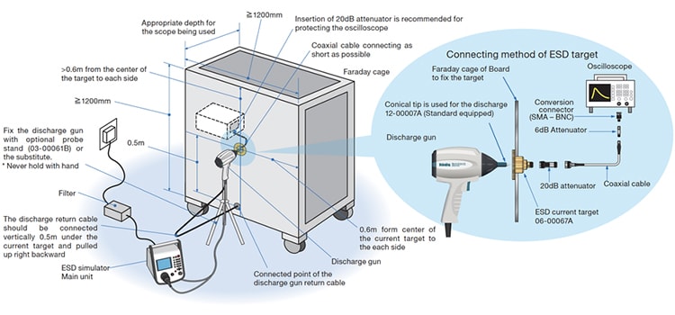
Calibration of target
Test setup and test procedure
Common Points:
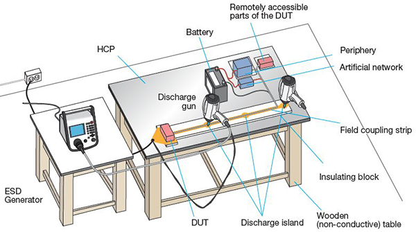
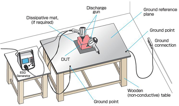
- Ground plane: at least 1.6 x 0.8m in size, at least 0.2m larger than the DUT or peripherals during setup, and with a connection resistance of 2.5mΩ or less.
- Insulating block: height 50±5mm. Extend 20mm beyond the test configuration on all sides.
- The DUT shall be connected to all peripheral devices required for functional testing of the DUT with the wire harness length of 1.7m (+0.3m- 0).
- All components should be at least 0.2 m apart from each other.
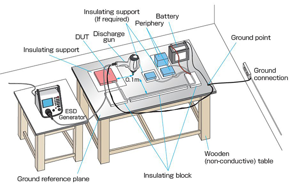
- Bundle the wire harness 0.1m away from the edge of the ground plane and secure it to the insulating block.
- The supply battery shall be on the test table, with the negative terminal of the battery directly connected to the GP.
- The test stand should be at least 0.1m away from other dielectric structures.
- For direct discharge, connect the electrostatic simulator's discharge return cable to the ground plane.
- Use discharge network of 150pF or 330pF depending on the EUT device location, and use 330Ω or 2kΩ.
- The test should be conducted for two or more test levels.
- Isolating block should be used for electronic equipment that are not directly chassis-mounted.
- Test at least 3 times with positive and negative polarity, separated by at least 1 second.
- Apply to every location available for human touch.
- Isolating block should be used for electronic equipment that are not directly chassis-mounted.
- The discharge electrode is brought into contact with the discharge point of the DUT before activating the discharge switch.
- For painted surfaces, if the coating is not an insulating coating, the pointed tip of the generator should penetrate the coating so as to make contact with the conducting substrate.
- The ESD discharge tip is held perpendicular to the surface of the DUT.
- After operating the discharge switch, move the discharge electrode tip to the DUT as quickly as possible (0.1m/s to 0.5m/s) until it contacts the discharge point and apply voltage.
- If the conductive material is declared to be an insulating coating, perform air discharge.
- Apply discharge to the ground plane with contact discharge.
- Test 10 times or more at intervals of 1s or more.
- Apply to the ground plane at points on each side of the DUT.
- Position the DUT so that the nearest surface is 0.1 m away from the edge of the ground plane that receives the discharge.
- Apply at a position 0.1m from the DUT and harness.
- Select 330pF as the CR constant depending on the mounting position of the device, and use 330Ω.
- At least 3 discharges shall be applied both to the positive and negative polarities with the interval not less than 1s.
- Select 150pF or 330pF as the CR constant depending on the mounting location of the device, and use 330Ω.
- Apply at least 10 contact discharges for each polarity to each discharge island with the time interval 1 s or longer.
- The CR constant is selected to be 330pF depending on the mounting position of the device, and 330 is used.
- Use 150pF capacitance and test with resistances that simulate direct contact with the human body (2kΩ) and touch with a metal object (330Ω).
- Conduct tests of two or more levels.
- At least 3 discharges shall be applied both to the positive and negative polarities with the interval not less than 1s.
- Contact discharge shall be applied to all locations human finger may touch.
- After applying the voltage, remove the static electricity from the DUT with a static elimination resistor of 1MΩ±20%, then energize it and confirm that it operates normally.
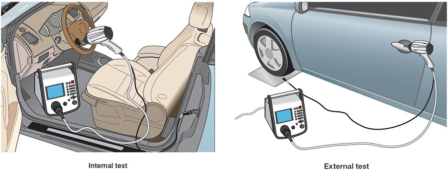
- Areas that can be easily touched by people inside the vehicle are tested with 330pF/330Ω or 2kΩ.
- Areas that can be easily touched by people from outside the vehicle are tested with 150pF/330Ω or 2kΩ.
- The ground wire connects to the chassis, such as the seat rail. During external testing connect to a nearby chassis or metal plate under the tire.
- Both the contact discharge and air discharge tests shall be done both for the internal and external tests.
Component immunity test method (powered-up test) - Direct contact and air discharge -
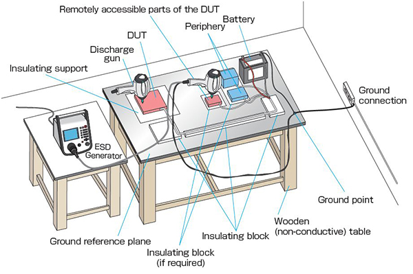
【 Contact Discharge 】
【 Air Discharge 】
Component immunity test method (powered-up test) - Indirect Discharge -
Component immunity test method (powered-up test) - Direct Discharge using FCP -
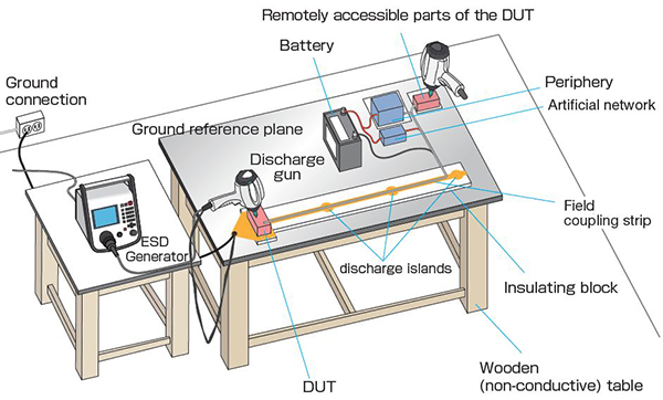
Component immunity test method (powered-up test) - Indirect Discharge using FCP -
Component immunity test method (unpowered) - Packaging and Handling - ESD Sensitivity Test
Vehicle test – Internal and external points –
Notes : This test set-up is quoted from ISO 10605 ed.3.0 (2023) Standard.
Please go through the Standard if more details are required.
Shinyei Corporation of America is the sole authorized distributor of NoiseKen products. We offer the most direct sales of NoiseKen products available in the US.


