



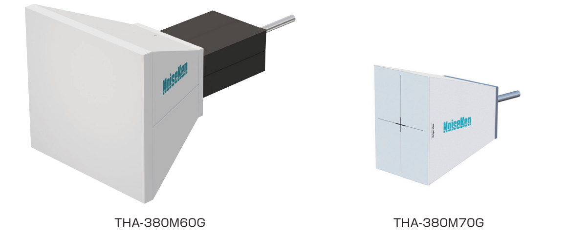
TEM Horn Antenna / THA-380M60G / THA-380M70G
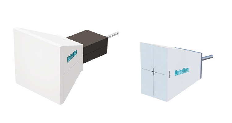
Prototype images
EMC Testing in the 5G/IoT Era!
The TEM horn antenna is an antenna for conducting a close proximity radiation immunity evaluation test (near electromagnetic field immunity test) of electromagnetic waves radiated from various wireless transmitters such as mobile phones and Wi-Fi equipment.
In the future, the close proximity radiation immunity evaluation test using the TEM horn antenna is expected to expand to various product standards such as medical equipment (IEC 60601-1-2) and multimedia equipment (CISPR 35).
NoiseKen's TEM horn antenna has a wide band, low VSWR, and wide electric field uniformity, offering an ideal solution for an efficient close proximity radiation immunity test.
This product is based on research results of the National Institute of Information and Communications Technology (NICT), Japan and joint research with Noise Laboratory Co., Ltd.
Features
- TEM horn antenna compliant with IEC 61000-4-39 Ed.1 standard.
- Allows testing to the entire frequency range of 380 MHz - 6 GHz with one antenna.
- Also supports 6 GHz band Wi-Fi "Wi-Fi 6E" (5.925 - 7.125 GHz).
- Low VSWR and high GAIN enable efficient electromagnetic wave radiation.
- Wide field uniformity reduces the number of times of movement of the antenna when radiating the EUT.
- Can be used for IEC 61000-4-3 preliminary testing in combination with a low-cost/low-output power amplifier by utilizing the proximity characteristics of the antenna.
Specifications
| THA-380M60G | THA-380M70G | |
|---|---|---|
| Parameter | Specifications | |
| Compliant standard | IEC 61000-4-39 | |
| Frequency range |
380 MHz - 6 GHz (8 GHz)
* Over 6 GHz not guaranteed |
380 MHz - 7.125 GHz |
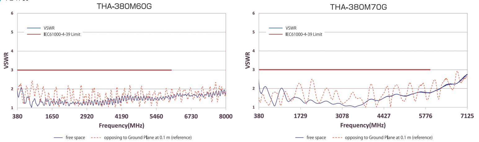
| VSWR | below 3 (refer to Figure "VSWR") |
Below 3 (refer to figure "VSWR")
* Over 6 GHz not guaranteed |
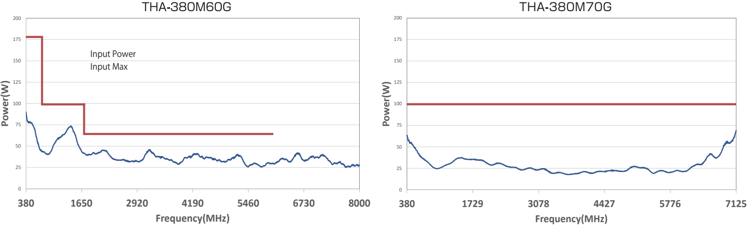
| Input power |
380 MHz - 750 MHz:180 W MAX
750 MHz - 1.7 GHz:100 W MAX 1.7 GHz - 6 GHz:65 W MAX |
380 MHz - 7.125 GHz:100 W MAX |
| Electric field uniform area | refer to figure "Electric field distribution characteristics" | |
| Required power | refer to figure "Power required for generating 300 V/m (typ) (at 0.1 m)" | |
| Impedance (typ) | 50Ω | |
| Connector | N (J) | |
| Dimensions |
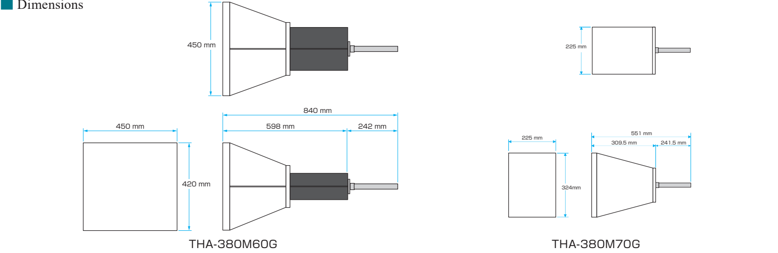
W450 mm × H420 mm × D598 mm
* Excluding protrusions, excluding φ22 antenna support pole * Refer to the figure "Dimensions" for details |
W225 mm × H324 mm × D309.5 mm
* Excluding protrusions, excluding φ22 antenna support pole * Refer to the figure "Dimensions" for details |
| Weight | approx.3.2 kg | approx.1.6 kg |
Dimensions
Antenna Characteristics
VSWR
Power required for generating 300 V/m (typ) (at 0.1 m)
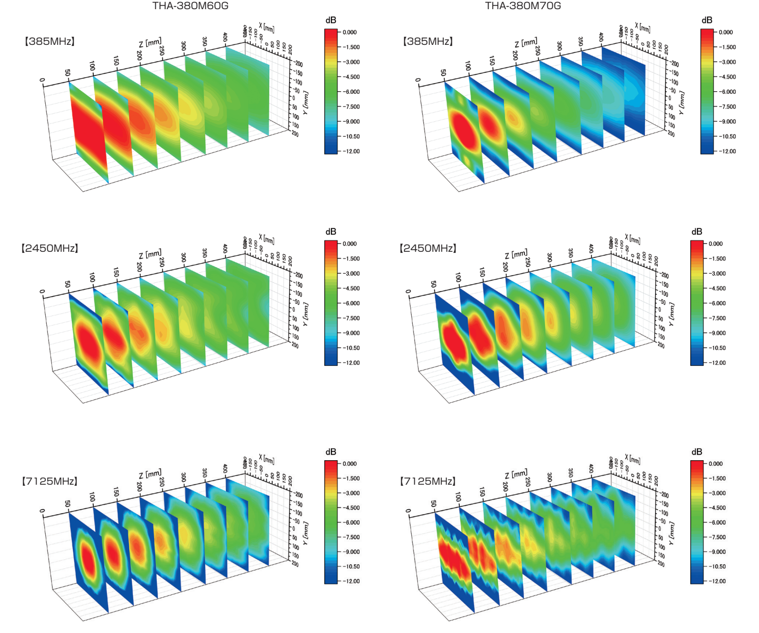
Electric field distribution characteristics
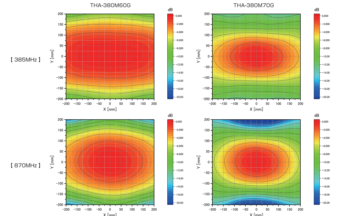
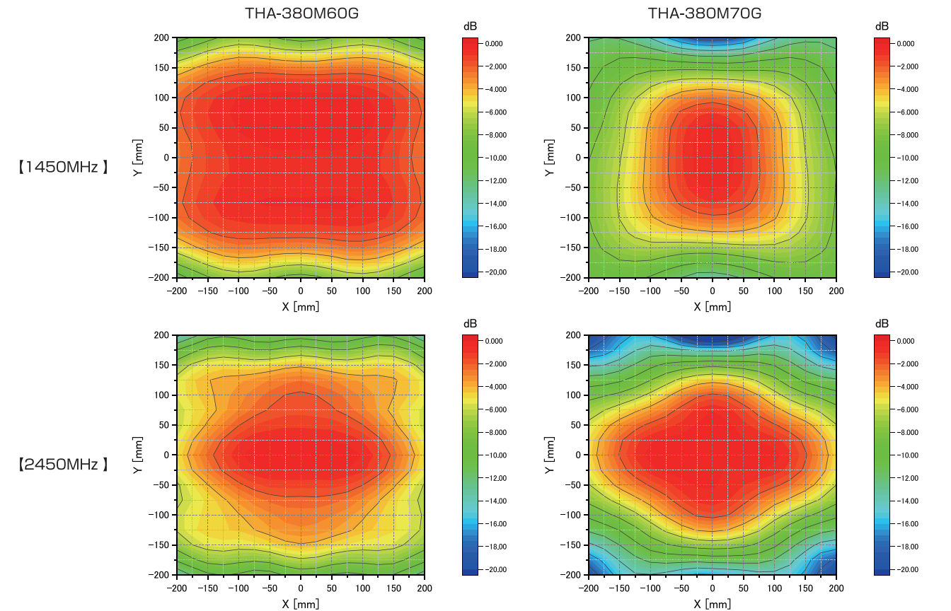
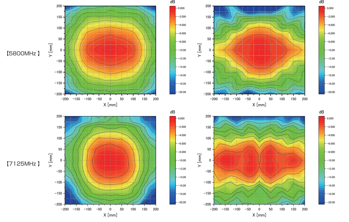
Antenna distance: 0.1 m.
2 dB / Line: The second contour line from the inside is the electric field uniform area.
The electric field distribution is vertically and horizontally symmetrical.
Close Proximity Distance Characteristics
Distance attenuation characteristics
Distance attenuation characteristics on axes with 100 mm from the antenna as the reference point.
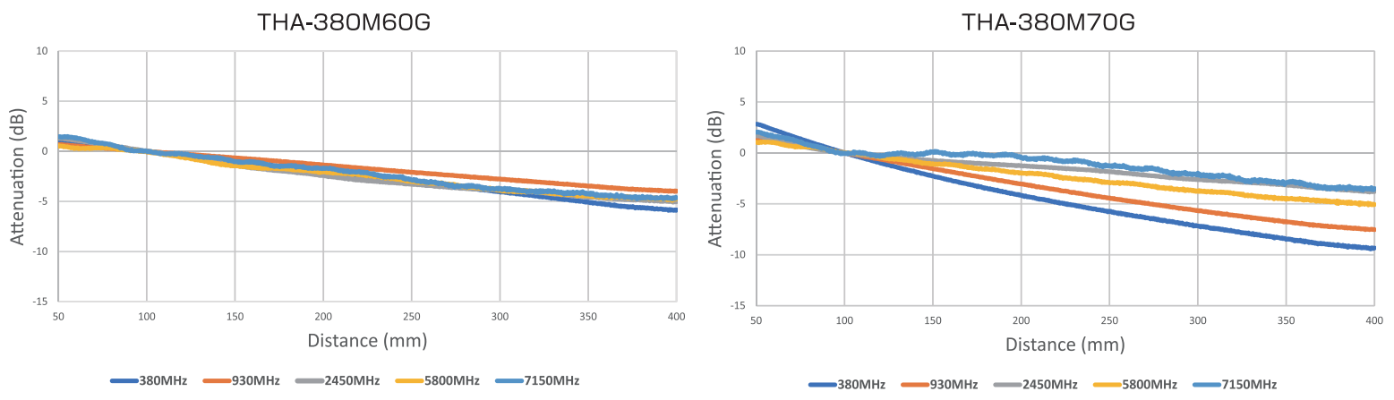
Electric field distribution distance characteristics
Reference point: maximum of 100 mm.
Securing Uniform Field Area
In the actual test, a quadrangle inscribed in the uniform electric field area is created to control the irradiation position. Therefore, a symmetrical electric field distribution characteristic that can create a large square with the maximum point in the center is required.
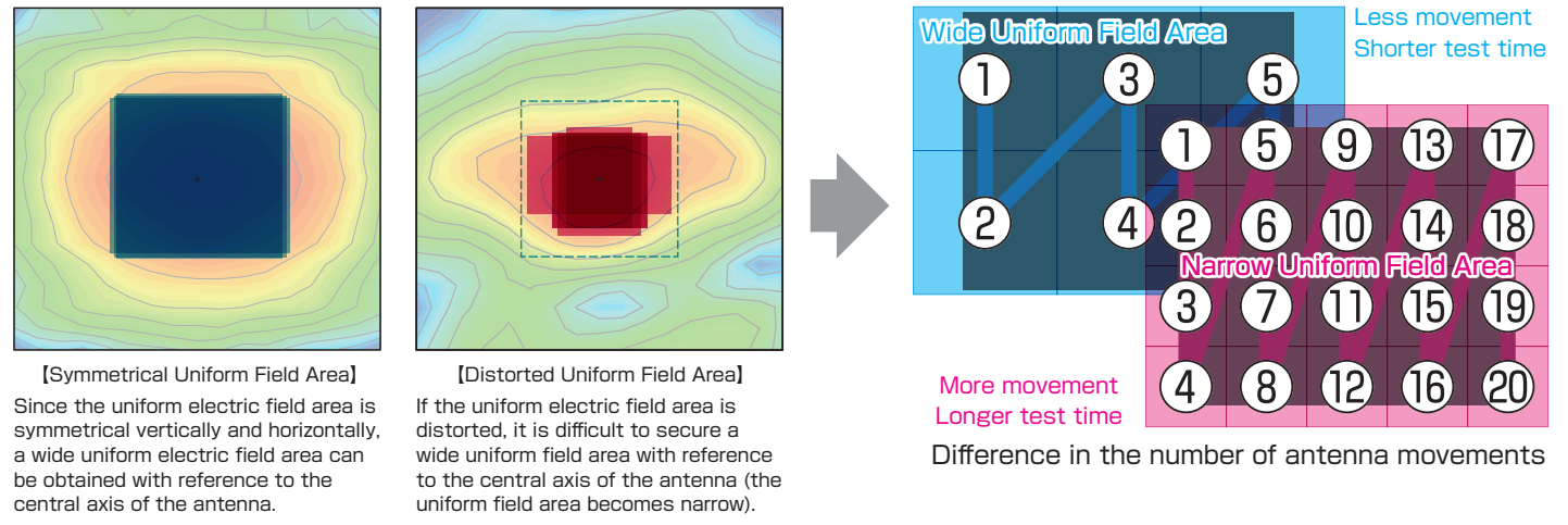
Symmetrical Uniform Field Area
Since the uniform electric field area is symmetrical vertically and horizontally, a wide uniform electric field area can be obtained with reference to the central axis of the antenna.
Distorted Uniform Field Area
If the uniform electric field area is distorted, it is difficult to secure a wide uniform field area with reference to the central axis of the antenna (the uniform field area becomes narrow).
Wide uniform field area: less movement and shorter test time. Narrow uniform field area: more movement and longer test time.
The wide and symmetrical electric field distribution characteristics contribute to shorter test time!
THA-380M60G and THA-380M70G Comparison Table
| THA-380M60G | THA-380M70G | |
|---|---|---|
| Dimensions, Weight | Good | Excellent |
| Frequency range | Excellent | Excellent |
| 8 GHz max (*guaranteed up to 6 GHz) | 7.125 GHz max | |
| VSWR | Excellent | Excellent |
| Good VSWR even when facing metallic surfaces | ||
| Required Power (for generating 300 V/m (typ) (at 0.1 m) | Good | Excellent |
| Electric field distribution | Excellent | Good |
| Distance attenuation characteristics | Excellent | Good |
|
Attenuation after the reference point is low, being
effective even for products with depth. |
Relatively large difference in attenuation
characteristics depending on the frequency. |
|
| Electric field distribution distance characteristics | Excellent | Good |
| Use in far-field test methods | Excellent |
N/A
Specifically designed as an antenna for close proximity radiation immunity testing |
System Configuration
The system consists of a signal generator serving as a signal source for noise, a power amplifier that amplifies the signal, a TEM horn antenna that emits radio waves, a power meter to check the power supplied to the TEM horn antenna and a software to control these devices.
The basic system configuration is almost the same with the IEC 61000-4-3 radiated immunity test. System setup for the proximity irradiation test can be achieved by simply switching the antennas from the broadband antenna to the TEM horn antenna.
Antenna position control (X-Y control) is available as an option.
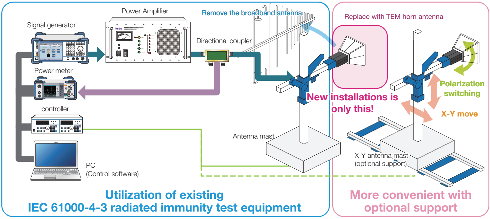
System configuration using the dedicated software
Test image using dedicated software (X-Y position movement and polarization switching control)
In the test, the distance between the DUT and the antenna is set to 100 mm, and all surfaces of the DUT are radiated with vertically polarized waves and horizontally polarized waves. By using the dedicated software to automate the antenna movement and radio wave radiation, you can further reduce test time and labor.
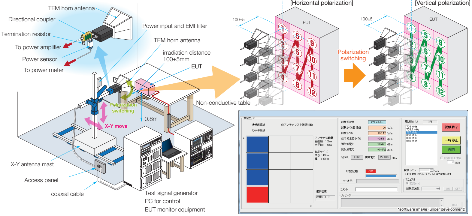
Software image: under development
The Need for Close Proximity Radiation Immunity Testing
With the advent of new communication technologies and infrastructures such as IoT and 5G, in addition to smartphones and wireless LANs, which have become extremely popular in recent years, a world is emerging in which many electronic devices are connected by wireless communication. On the other hand, from the perspective of EMC, the number of cases where these wireless transmitters are in close proximity to other electronic devices is increasing, raising concerns about the risk of electromagnetic interference. Against this background, IEC 61000-4-39, an electromagnetic immunity test method for nearby transmitters, was issued. Since the electromagnetic field generated by a nearby transmitter is extremely strong and has the characteristics of the near field, it is necessary to perform it in addition to the conventional radiated immunity test that radiates from a distance. The basic standard IEC 61000-4-39 defines the antenna to be used, and it is necessary to use a TEM horn antenna in the frequency band of smartphones, mobile phones, and 5G (sub6).
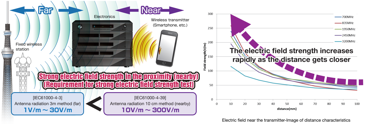
The electric field strength increases rapidly as the distance gets closer. Strong electric field strength in the proximity requires a strong electric field strength test.
Distant Radiation and Proximity Radiation
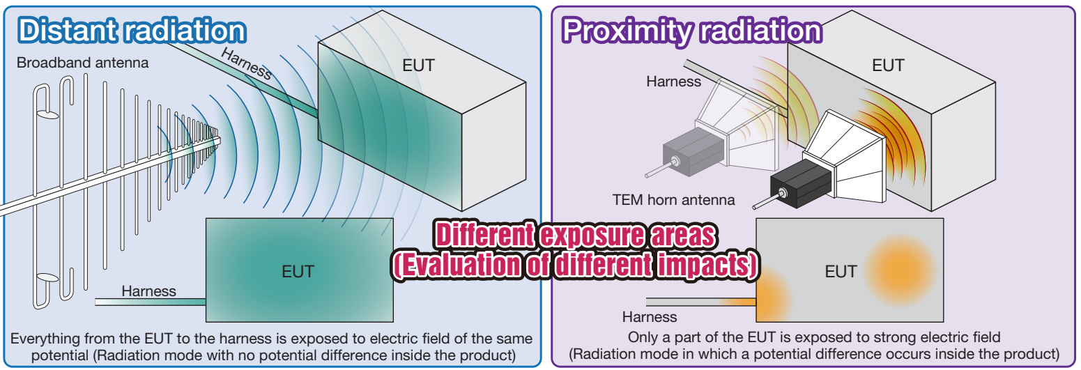
Distant radiation: Everything from the EUT to the harness is exposed to electric field of the same potential (radiation mode with no potential difference inside the product).
Proximity radiation: Only a part of the EUT is exposed to strong electric field (radiation mode in which a potential difference occurs inside the product).
Test Conditions and Results
- Product: Automotive navigation system
- Modulation: PM
- Frequency: 900 MHz
- Evaluation: 1 kHz audio signal

This test is the result of the test conducted in accordance with the proximity radiation immunity test standard (ISO 11452-9) for automobile equipment. Both distant and close proximity radiation testing are already being conducted for vehicles and in-vehicle equipment.
Different test conditions show different test results.
Shinyei Corporation of America is the sole authorized distributor of NoiseKen products. We offer the most direct sales of NoiseKen products available in the US.